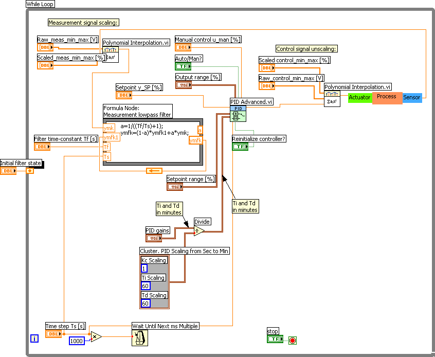
You can use this window to configure the simulation loop to handle timing with this particular VI. to bring up a configuration dialog window. Because the PID algorithm is going to run on a Real-Time based operating system with a fixed loop rate, right-click on the PID.vi and select SubVI Node Setup…. On the function palette, select the Control Design & Simulation->PID subpalette and drag and drop the PID.vi into the Control & Simulation Loop. Now double-click on the Transfer Function block to input the transfer function parameters.įigure 3. This places a Transfer Function block inside the Control & Simulation Loop. Create a Control & Simulation Loop.Īgain on the Simulation subpalette, select Continuous Linear Systems and click once on Transfer Function and once inside the Control & Simulation Loop you created previously.

On the Functions Palette, select Control Design & Simulation->Simulation->Control & Simulation Loop then click and drag to size and create a Control & Simulation Loop.įigure 1. Start by opening the LabVIEW Development Environment and navigating to the Block Diagram. Your goal is to implement a PID algorithm that is going to run on a Real-Time controller with a loop rate of 1000 Hz (0.001 second period). If you replace the numeric values, you get the following transfer function: For the sake of simplicity consider a basic transfer function for a DC motor where effects such as friction and disturbances are being considered:ī is the Friction Torque Constant (1.8E-6 N-m-s) The performance confirms the functionality of the developed set up.In this tutorial, we will design the velocity controller for a DC motor. The performance of the developed set up is checked with different controller tuning conditions as well with different coupling condition of MIMO process. With the help of this interface the user can easily deployed any newly developed algorithm and verify on this laboratory scale test set up. The proposed set up has capability to interface with user friendly LabVIEW platform. An attempt is made to develop low cost, configurable, computerized and smaller size multi input multi output coupled process control laboratory test setup.

Computerized and easy to use laboratory scale set up is very essential to investigate performance of different control algorithm on MIMO process. Even after very significant efforts made by the research fraternity, control of coupled MIMO process is still an open research issue. Control of such MIMO processes is always challenging due to coupling between inputs and outputs. Multi Input – Multi Output (MIMO) processes are very commonly found in many chemical unit processes.


 0 kommentar(er)
